We need your feedback!
Please take the following survey after completing Lab 2. As you go through the lab, remember or write down how helpful each video is, what could be made better, what you struggled with, etc. We will take any feedback we can get!
Please take the following survey after completing Lab 2. As you go through the lab, remember or write down how helpful each video is, what could be made better, what you struggled with, etc. We will take any feedback we can get!
Lab 2
Lab 2 will deepen your understanding of sketches, introduce geometry query and selections, and teach basic feature creation. You will then create two scripts, one to calculate the length of a pulley belt, and another to create the pulley geometry.
Objective
Create an understanding of selections, geometry query, inputs, and feature creation.
Deliverables
There will be two deliverables for lab 2. Deliverable 1 will be creating a belt length calculator. Deliverable 2 will be to use sketches from Lab 1, as well as additional sketches, to create a pulley.
Geometry Selection and Query
Geometry selection and querying is important when creating features or gathering part data. Lab 2 will use two methods to select and query geometry. The first will be asking the user to select two points. These two points will be then used to calculate the needed belt length if two pulleys of certain radii were placed at those points. The second method of selecting geometry is through querying a component's geometry through the API.
User Selections
The following video shows how users can be asked to select certain geometry. Once selected, the geometry can then be used for many purposes, such as feature creation. We will be using the selected geometry to calculate the belt length.
User Selections
The following video shows how users can be asked to select certain geometry. Once selected, the geometry can then be used for many purposes, such as feature creation. We will be using the selected geometry to calculate the belt length.
Lab Practice
Create a new script. In this script, use selectEntity to get two points that the user selects
Geometry Query via the API
Geometry can also be queried and selected using the API without any user input. Following the object model, geometry such as bodies, faces, edges, or profiles can be found and selected. Often you will need to receive information about an object, or use an object as an input. For example, when creating an extrude, you will need to pass in the profile to be extruded, and that profile can be queried through the API.
One application for selecting a face is for creating sketches. In order to create a sketch on a face other than a coordinate plane requires querying and passing in a face off of a component body.
Lab Practice
Using the code from Lab 1, query the profile geometry from the two circles that were created. This profile will be needed to create the extrude for the pulley geometry.
Using the code from Lab 1, query the profile geometry from the two circles that were created. This profile will be needed to create the extrude for the pulley geometry.
Input Objects and Feature Creation
Feature Creation
Feature creation is the driver behind CAD modeling. In order to create a feature, you will need to access certain collections, use methods to create the feature, and pass in input objects. the next video is a basic overview of the feature creation process, focusing on accessing the correct collections and using the right functions. This video quickly goes over feature creation.
Feature creation is the driver behind CAD modeling. In order to create a feature, you will need to access certain collections, use methods to create the feature, and pass in input objects. the next video is a basic overview of the feature creation process, focusing on accessing the correct collections and using the right functions. This video quickly goes over feature creation.
Input Objects
To create a feature, several input objects must be passed in. For example, if an extrude was being created, the regular Fusion 360 interface would open a dialog and prompt the user for several inputs (ex: which profile to extrude, direction, distance, etc). Similarly, when we create a feature using the API, we must give it inputs like the profile, direction, distance, and feature operation. The following video builds off the previous video to walk through two examples of input objects. It will use input objects to create an extrude and a circular pattern feature.
Lab Practice
Still building off the code from Lab 1, extrude the first circle.
Still building off the code from Lab 1, extrude the first circle.
Open Lab
Objective
Create an understanding of selections, geometry query, inputs, and feature creationCreate a basic understanding of scripts, Spyder, and sketches.
Deliverables
There will be two deliverables for lab 2. Deliverable 1 will be creating a belt length calculator. Deliverable 2 will be to use sketches from Lab 1, as well as additional sketches, to create a pulley.
Part 1
Using userInterface.selectEntity, ask the user to select two points. Calculate the length of a belt if there were two pulleys at those two selected points. The belt length should consider the radii of the two pulleys. Output the answer to the users screen.
Part 1 Help Hints
Once two points are selected by the user, you can use easily calculate the distance between the two points by using the Points3D.distanceTo method. It is necessary to realize though that when the user selects two points, a selection object is returned, not a point. From that selection object, you can get the point of that object and use that in Point3D.distanceTo(). Below is some code that illustrates this principle.
|
# Get the User Interface
ui = app.userInterface # The needed parameters for selectEntity are (Prompt, filter) selectedEntity = ui.selectEntity("Select a Point", "SketchPoints,Vertices,ConstructionPoints") # Grab the point from the entity selected selectedEntityPoint = selectedEntity.point |
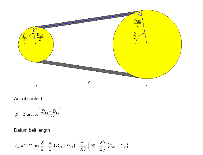
Once you have the distance between the two chosen points, you can use the pulley diameters to calculate the overall belt length. You can use the diagram below, or this reference, to see the math needed to calculate the length of a belt going around two pulleys. Dd1 and Dd2 refer to the diameters of the two pulleys
In order to do any math operations beyond basic addition/subtraction/multiplication/division you will need to import the math library at the beginning of your code. Math operations in python have the syntax of math.operation. For example, to do the square root of a value, the syntax would be math.sqrt(value).
Outputting the response to the screen can be done by using a message box. The code below is an example of outputting the needed belt length, if the belt length was already calculated and assigned to the variable BeltLengthVariable. Notice the two lines of code below dealing with the units manager. This is needed to display the number out to the user.
Outputting the response to the screen can be done by using a message box. The code below is an example of outputting the needed belt length, if the belt length was already calculated and assigned to the variable BeltLengthVariable. Notice the two lines of code below dealing with the units manager. This is needed to display the number out to the user.
|
# You will also need to get the application and design instance in order to display the value in correct units
app = adsk.core.Application.get() design = app.activeProduct # Now we can convert our belt length variable into a displayable format unitsMgr = design.unitsManager displayBeltLength = unitsMgr.formatInternalValue(beltLengthVariable, unitsMgr.defaultLengthUnits, True) ui.messageBox('The needed belt length is: ' + displayBeltLength) |
Part 2
Using the sketch from Lab 1, as well as additional sketches, create the pulley geometry. Use input objects to create features such as extrudes and patterns. Below is an example of what the pulley could look like.
Using the sketch from Lab 1, as well as additional sketches, create the pulley geometry. Use input objects to create features such as extrudes and patterns. Below is an example of what the pulley could look like.
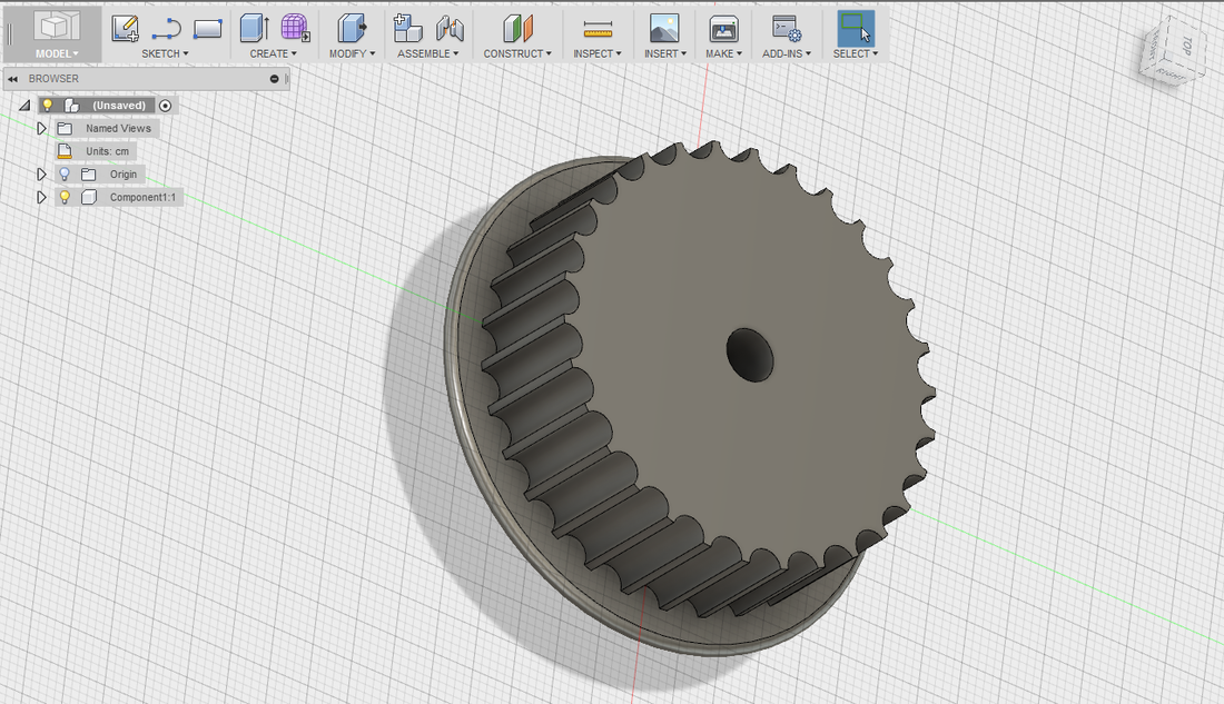
For the pulley, you will need at least four sketches with circles. The first will be the circle to create the main body, the second will be a small circle to create the teeth, the third will create the center hole, and the fourth will create the back flange.
The radius of the first circle should be driven by a variable that specifies the number of teeth. The teeth (which come from the second circle) will have a radius of 1.56 mm, and are spaced 5 mm apart (center to center) along the curvature of the first circle. Extrude the first circle as a new body, do a distance of 1.5 cm. Extrude the second circle as a cut, and then pattern that feature around the first extrude, effectively creating teeth on the main body. Create a third circle with radius of 0.5 cm at the center and extrude it as a cut to create a center mounting hole for the pulley. The fourth circle should be slightly larger than the main body, and should be 0.2 cm thick. Extrude and join it with the main body.
The radius of the first circle should be driven by a variable that specifies the number of teeth. The teeth (which come from the second circle) will have a radius of 1.56 mm, and are spaced 5 mm apart (center to center) along the curvature of the first circle. Extrude the first circle as a new body, do a distance of 1.5 cm. Extrude the second circle as a cut, and then pattern that feature around the first extrude, effectively creating teeth on the main body. Create a third circle with radius of 0.5 cm at the center and extrude it as a cut to create a center mounting hole for the pulley. The fourth circle should be slightly larger than the main body, and should be 0.2 cm thick. Extrude and join it with the main body.
Part 2 Help Hints
Sample code can be found online for extrudes and circular patterns. Be aware that the sample code is patterning a body, but you will need to pattern a feature. Instead of passing into the input entity a body, pass it in the second extrude feature (the extrude feature used to cut away at the main body). For this lab and the following labs, we want to drive the size of the main pulley from the number of teeth. Lab 1 created the first sketch off of a radius value. Simple math can be done to convert the number of teeth wanted into the radius of the first circle:
Sample code can be found online for extrudes and circular patterns. Be aware that the sample code is patterning a body, but you will need to pattern a feature. Instead of passing into the input entity a body, pass it in the second extrude feature (the extrude feature used to cut away at the main body). For this lab and the following labs, we want to drive the size of the main pulley from the number of teeth. Lab 1 created the first sketch off of a radius value. Simple math can be done to convert the number of teeth wanted into the radius of the first circle:
Circumference = (Number of Teeth) * (Space Between Teeth)
Radius = (Circumference) / (2π )
Radius = (Circumference) / (2π )
Remember, the space between the teeth is 5mm.
Additional Practice
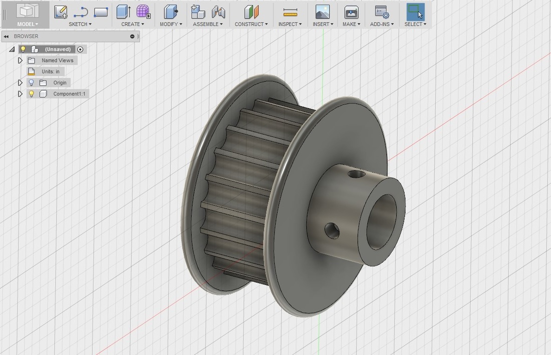
For additional and expanded practice with features, try filleting the edges of the flange. A second flange could also be created, with its edges filleted. A separate extrude with threaded holes could also be made for set screws to secure the pulley down onto a shaft, similar to the pulley shown below. Look up other pulleys online for more ideas on creating a custom pulley and expanding your knowledge and skills in the Fusion 360 API.
For additional and expanded practice with features, try filleting the edges of the flange. A second flange could also be created, with its edges filleted. A separate extrude with threaded holes could also be made for set screws to secure the pulley down onto a shaft, similar to the pulley shown below. Look up other pulleys online for more ideas on creating a custom pulley and expanding your knowledge and skills in the Fusion 360 API.